The next step consists of generating segments which represent tissues of interest.
Pixel Value Distribution
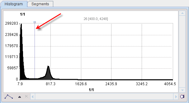
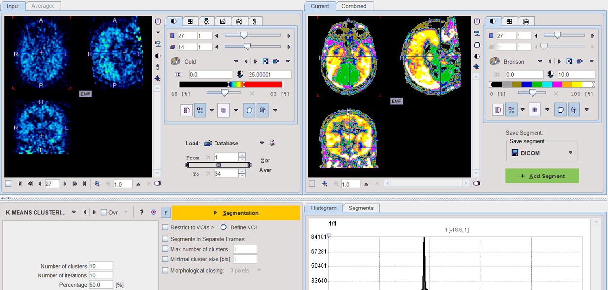
The Histogram in the lower right provides an overview of the pixel value distribution in the current image volume. It may indicate a peak usable for setting a background threshold. The current threshold value is indicated by the vertical line in the histogram.
Segmentation Method Selection
The segmentation method for defining the pixel inclusion criterion is selected by the list selection. Each method has its own parameters which are described below. A preview facility is available to get an impression of the performance, although it is not effective for all methods. It is enabled by the Ovr box. Consequently, the pixels which satisfy the criterion highlighted in the image overlay. This works best if the image uses the Gray color table.
CAVEAT: Overlay updating might be slow for high-resolution data sets. In this case it is worthwhile switching the Ovr box off for most of the time.
Segmentation
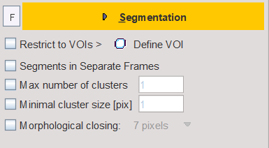
The Segmentation button starts the actual segmentation on the selected image. The F toggle button in front of the Segmentation button is applicable for dynamic Input images. If it is enabled, only the currently shown frame is processed, otherwise all of the dynamic frames resulting in a "dynamic segment". The purpose of dynamic segmentation is to construct an object which can be animated over time.
The result is shown in the Current tab to the right, overwriting any existing content. The Add Segment button appends the Current segment to the Segments list, an also adds it to the Combined display.
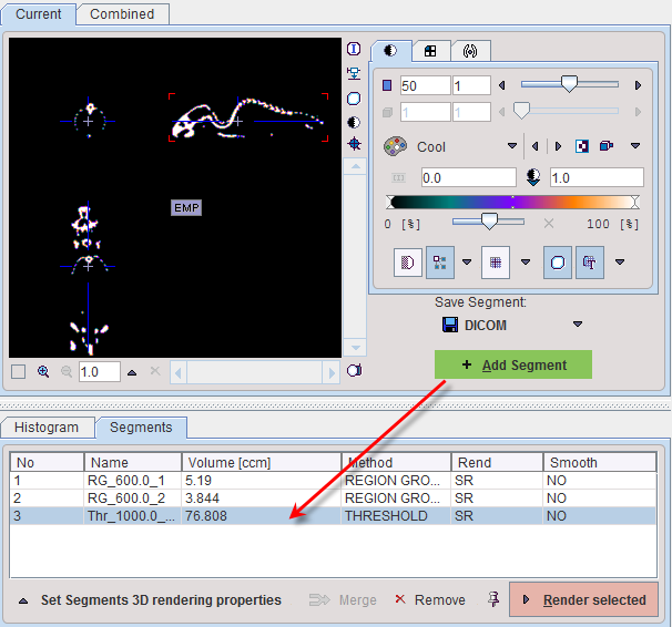
The No entry in the Segments list indicates the number by which a segment is identified in the Combined image, Name provides some descriptive information, Volume its physical volume, and Method identifies the applied segmentation method. Multiple segments in the list can be selected and transformed into a single segment by the Merge button. Hereby, the initially distinct values are replaced by a common value, and the original list entries deleted.
Segmentation with VOI Masking
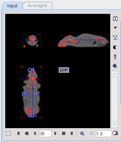
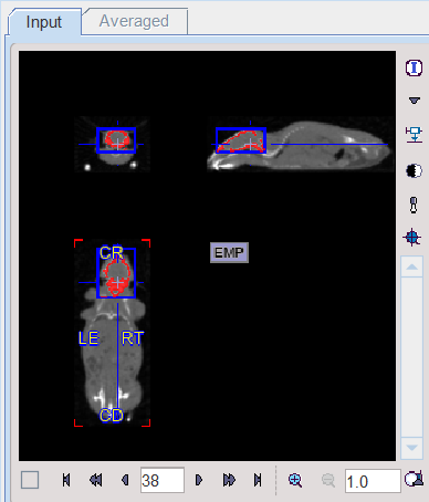
In certain circumstances, the segmentation methods alone may not be sufficient for separating an object from other structures. If this happens, the user can define a VOI which prevents segmentation from leaving the area of main interest. To do so, the Restrict to VOI(s) box has to be enabled and the Define VOI button activated. The VOI tools interface appears and allows drawing a VOI. In the example below a cuboid object VOI was centered on the mouse head.
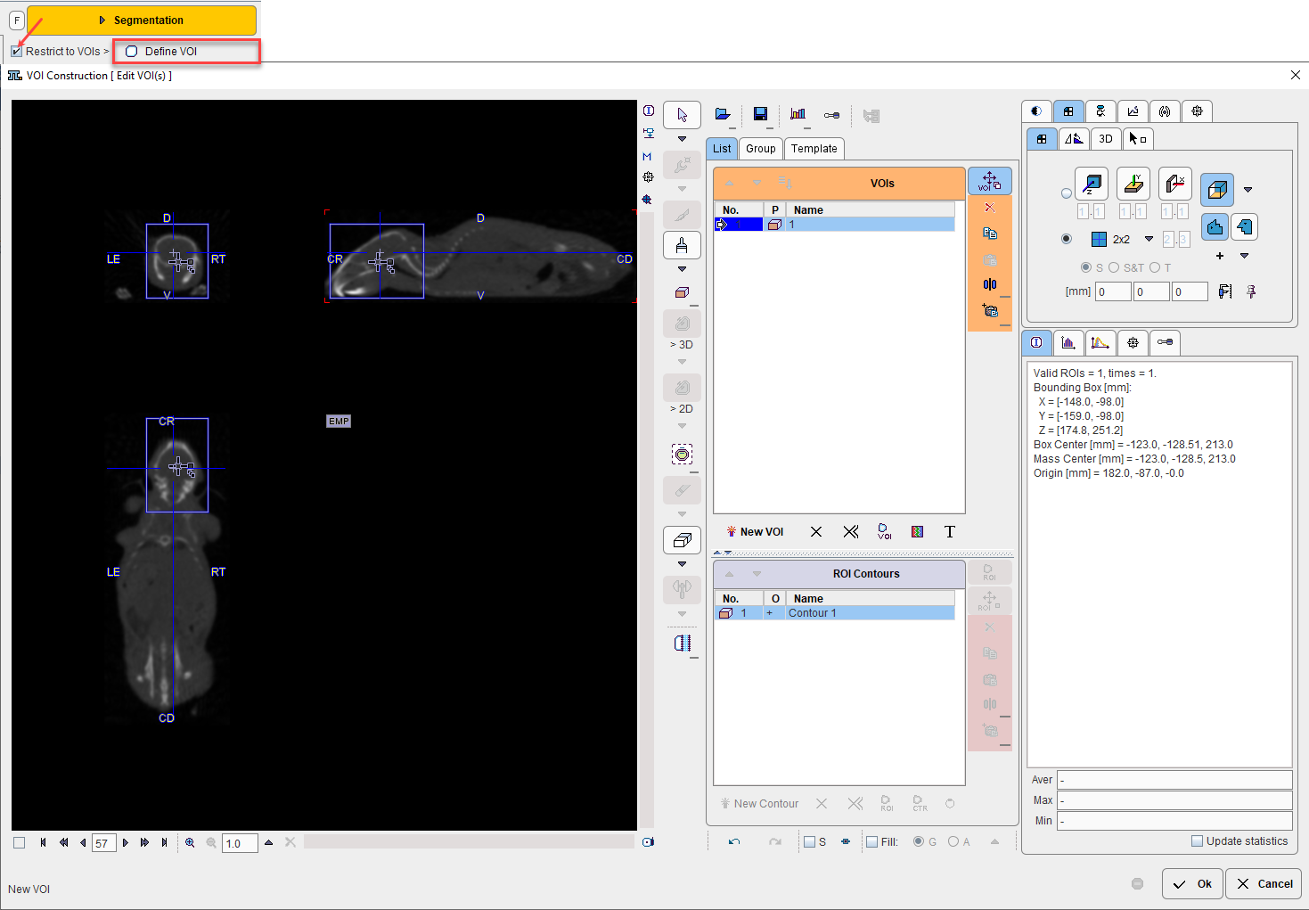
Closing the VOI tools with the Ok button confirms the VOI definition, and the criterion is only applied within the VOI.
•Segments in Separate frames: when enabled, allows organizing multi-segments results as a dynamic image: one segment per frame.
•Max number of clusters: when enabled it performs a cluster analysis and limits the number of clusters per segment according to the specified value.
•Minimal cluster size [pix]: when enabled it performs cluster analysis and includes in the segmentation results only cluster larger than the specified size.
•Morphological closing: when enabled it performs a morphological closing operation per segment according with the selected option: 3, 5 or 7 pixels.
Saving Segments
While standard segmentations create binary images with 0 (background) and 1 (segment) pixel values, there are clustering approaches which generate multiple segments in a single calculation. These segments are distinguished by increasing integer pixel values as illustrated below with the result of a k-means clustering of the dynamic uptake.
The Current segment or the Combined segments can be saved as images in any of the supported formats using the Save segment button.