This segmentation method implements two main approaches for the active contours models (or Snakes) methodology based on energy calculation:
1.Edge based models: utilize the image gradient to guide the evolving curve toward object boundary.
2.Region based models: the energy is treated as an inequality between regions inside and outside the model, therefore the model tends to move onto areas of similar feature (e.g. homogeneity).
Both methods request an initial VOI, which is modified iteratively to find the least energetic state.
1. Edge Based
This segmentation implements several variants of edge based active contours methodology:

There are two relevant parameters, Field and Energy settings.
The Field selection determines how the energy is calculated and has the choices:
•Gradient: calculates a simple image gradient using pixel values differences;
•Sobel: calculates the image gradient using the Sobel digital filter;
•GVF: gradient vector flow algorithm, which calculates image energy iteratively;
•GGVF: generalized gradient vector flow algorithm, with better convergence than GVF.
Each of the Field selections has its own parameters. For GVF and GGVF:
•Iterations: Number of iterations.
•mu: Smoothness of the energy field.
•time step: Speed of the algorithm convergence. Values bigger than one can cause algorithm instability.
The Energy Settings are
•Vertices per contour: Number of contour nodes.
•Number of iterations: Number of contour modifications before the algorithm stops.
•Alfa: Hooke's constant of contour tension.
•Beta: Contour rigidity/stiffness against bending.
•Gamma: Impact of the external force field.
2. Region Based
The region based models make use of statistical information of region instead of using image gradient, offering better performance in case of noise and weak boundaries or discountinuous boundaries.

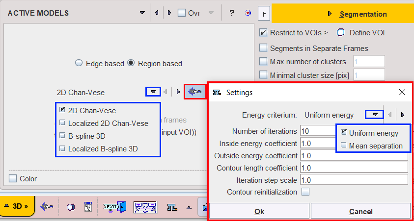
The 2D Chan-Vese model has been successful in handling images with homogeneous regions. It is a 2D algorithm. In case of MR, PET or CT images affected by shading artefact this method is not effective for segmenting objects with intensity inhomogeneity.
The Localized version of 2D Chan-Vese algorithm takes into consideration just the neighbourhood of the analyzed node instead of a global image space. The algorithm is slower (energy is calculated NxM times instead of just once) but much more accurate.
In both Chan-Vese implementations the Energy criterium determines how the energy is calculated and has two choices:
•Uniform energy: the energy models the foreground and background as constant intensities represented by their means. In particular, the modeling flow finds its minimum energy when the interior and exterior are best approximated by means. In the localized version, the minimum is obtained when each point on the curve has moved such that the local interior and exterior about every point along the curve is best approximated by local means.
•Mean separation: this energy relies on the assumption that foreground and background regions should have maximally separate mean intensities. Optimizing the energy causes the curve to move such that interior and exterior means have the largest difference possible. The optimum of this energy is obtained when local means are the most different at every point along the contour. In some cases, this is more desirable than attempting to fit a constant model. In the current implementation the local foreground and background means are encouraged to be different rather than constant. This allows this energy to find image edges very well without being distracted when interior or exterior regions are not uniform.
For both type of energy criterium the below parameters can be set:
•Number of iterations- defines the maximum number of iteration at which the algorithm is stopped. It is an iterative algorithm: for each iteration the energy is calculated and compared to the one from the previous step.
•There are three energy components: energy outside the contour, energy inside the contour and energy resulting from the contour length. The Inside energy coefficient, Outside energy coefficient and Contour length coefficient define the impact of each energy type on the overall energy. The coefficient with the highest value has a greater impact in the energy calculation. Please note that only the ratio between the coefficients is taken into consideration, i.e. 1.0, 1.0, 1.0 returns the same result as 2.0, 2.0, 2.0. ;
•Iteration step scale defines the factor by which the calculated movement of the contour in each iteration is multiplied. For example, based on the energy, the contour should be moved to the left side by 2 millimeters. If the parameter is set to a value of 2.0, the contour will be moved to the left side by four millimeters.
•Contour reinitialization - if enabled, the contour is reinitialized in each iteration (i.e. its state after previous iteration is described using zero level set once again).
In case of the B-spline 3D model the surface/contour is only sampled at some points and approximated between them using b-splines. The energy formulations are similar to Chan-Vese basics. This framework allows real-time 3-D segmentation since it reduces the dimensionality of the segmentation problem.

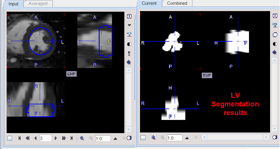
An example would be the extraction of the left ventricle from the cardiac MR studies. The results obtained with the settings above are illustrated below:

The Energy criterium - defines the way of energy calculation. Two options are available:
•Uniform energy: prefers the state when the areas with similar pixel values are grouped at different size of the contour/surface.
The following parameters are available for setting:
•Reduction (X,Y,Z): allows creating simplified surface based on data simplification. The defaults value is 1 and is representing the smallest value to be defined. Initially, the program will use this number and multiply the pixel size of the data with this value. Finally, the surface will be generated on the new data. It is a faster procedure and the results will consist in surface being less precise.
•Neighborhood size (X, Y, Z): allows defining the size of the neighborhood in each direction in mm. The values are used to automatically calculate the Neighborhood size in pixels (X, Y, Z)
•Maximum number of iterations: defines the maximum number of iterations at which the algorithm is stopped.
•Maximum number of iterations in wrong direction - defines the maximum number of interations allowed in case there is a number of subsequent iteration with energy increase. In such situation the algorithm is stopped and the current state is treated as a local minimum. The "wrong direction" is identified when after contour modification the overall energy is higher than previously.
•Step increase scale - factor by which iteration step scale is multiplied after each successful iteration.
•Step decrease scale - factor by which iteration step scale is divided after each "wrong direction" iteration
•B-spline degree - degree of a b-spline function approximating the surface.
•Theta/Phi spacing (radius) - a radial space between two neighbouring nodes of a surface (in degrees).
•Iteration step scale - defines the factor by which the calculated movement of the contour in each iteration is multiplied. For example, based on the energy, the contour should be moved to the left side by 2 millimeters. If the parameter is set to a value of 2.0, the contour will be moved to the left side by four millimeters.
References
1.Mark A. Heidekker, Advanced Biomedical Image Processing. ;John Wiley & Sons, ;29 mar 2011 ;- 528, Chapter 6: Active models.
2.Tony F. Chan, Luminita A. Vese, Active Contours Without Edges, IEEE Trans. Image Process. Feb 2001; 10(2):266-277.
3.Chenyang Xu, Jerry L. Prince. Snakes, Shapes, and Gradient Vector Flow. IEEE Trans. Image Process. March 1998; 7(3):359-369
4.Barbossa et al, B-Spline Explicit Active Surfaces: An Efficient Framework for Real-Time 3-D Region-Based Segmentation. IEEE Trans. Image Process. Jan 2012; 21(1):241-251,
5.Shawn Lankton, Allen Tannenbaum. Localizing Region-Based Active Contours, IEEE Trans Image Process. Nov 2008; 17(11): 2029–2039. doi:10.1109/TIP.2008.2004611