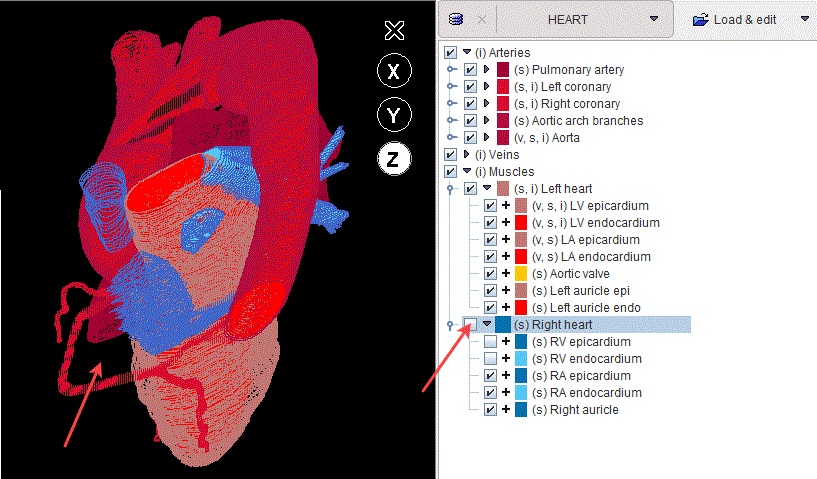
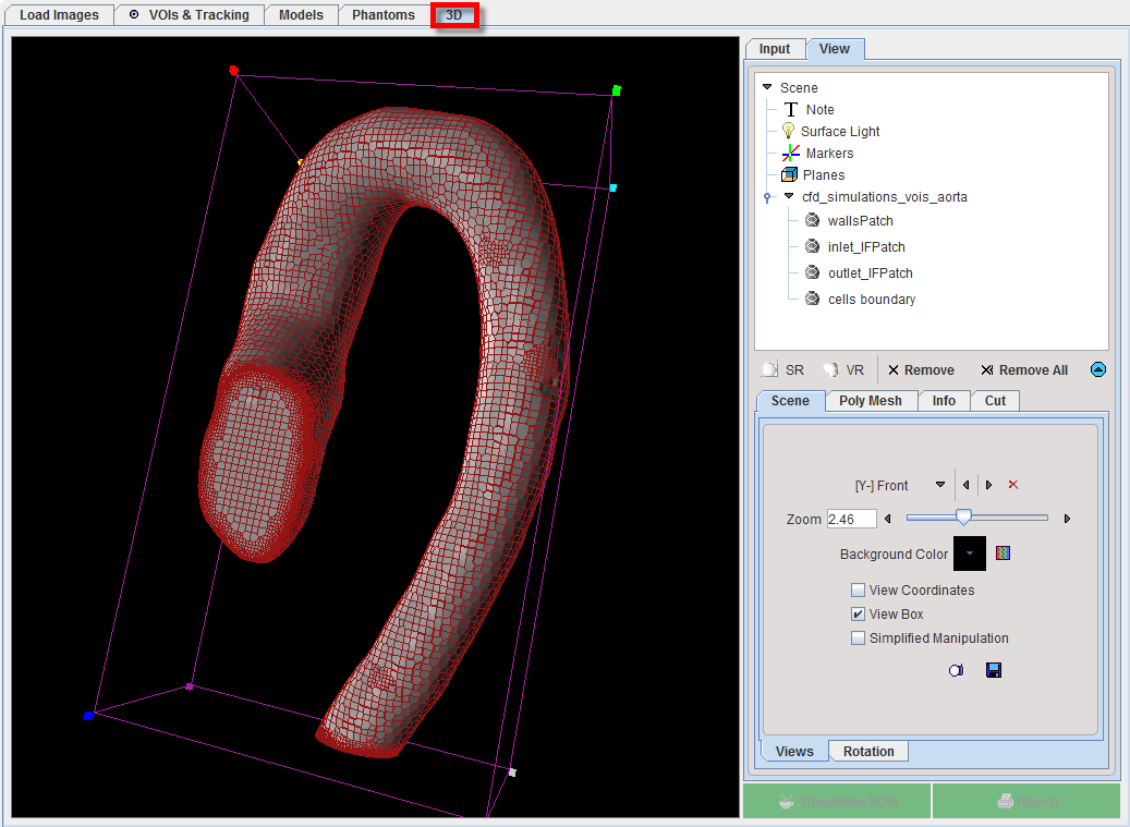
The result of adding VOIs to the model is structurally organized in the model tree on the Models page.
The selection of a subset of elements in the model is supported by the dedicated panel as illustrated below:

The model structure is organized as a hierarchical tree on three levels: top, middle and low level. The hierarchy corresponds to the Selected VOIs destination settings defined in the model builder interface during the VOI addition.
The branch on the top level is represented by the Group, e.g. the BrainVessels, as indicated in the left panel. It corresponds to the Anatomic Group defined in the model builder interface.
The full tree can be opened easily by the button indicated in the right panel. The middle level entry in the model tree is represented by the Structure node, e.g. the Aneurysm. It corresponds to the Structure defined in the model builder interface.
The single entry in the tree is called Element and corresponds to a VOI in the VOIs list. It represents the low level entry in the model hierarchy, e.g. Vessels.
In general, the Structure node consists of at least one Element. The Group consists of at least one structure node. A model may consist of one or several groups of structures. An example of such model (HEART) is illustrated below:
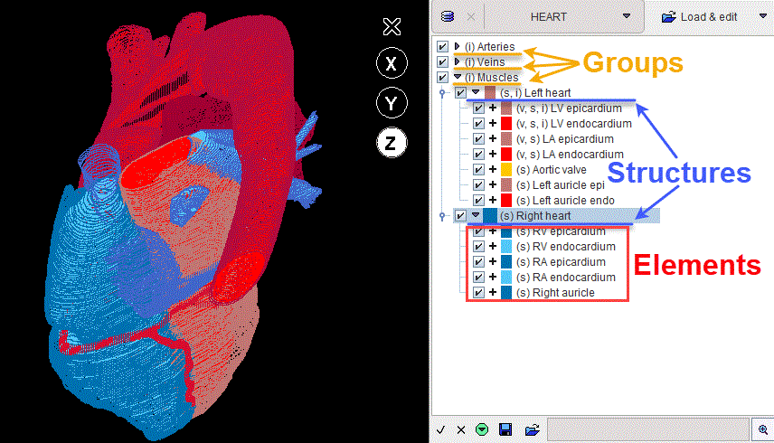
It consists of three groups: Arteries, Veins and Muscles. Each group contains multiple structure nodes: e.g. the Left heart and Right heart in the Muscles group.
Round brackets are used to add encoded information for each entry in the model tree. Such information precedes the name of the entry and is summarized in the table below:
s |
Stands for surface mesh and indicates that a VOI was added to the model as geometry. STL structure is auto-generated and saved for each such VOI. Note that each middle and low level entry in the model tree has such information available. When an element is selected in the model tree a preview of the simplified mesh structure is shown in the viewport. |
c |
Stands for case and indicates that a CFD simulation result was linked to the selected entry in the model through the local cases manager. When such encoding is available for a selected entry in the model tree the
|
i |
Stands for image and indicates that at least one image was defined as characteristics for that entry. |
v |
Stands for volume mesh. The volume meshes are generated in the process of the CFD case creation and they can be linked with the model element through the local cases manager. |
Tree Manipulations
Branches in the tree can be opened/closed with the little arrows left to the branch names.
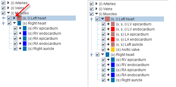
Tree Selections
The structures of interest are the ones with checked boxes to the left of their color code. Simply click into a box for changing the selection. In the example below the RV epicardium and RV endocardium have been de-selected.
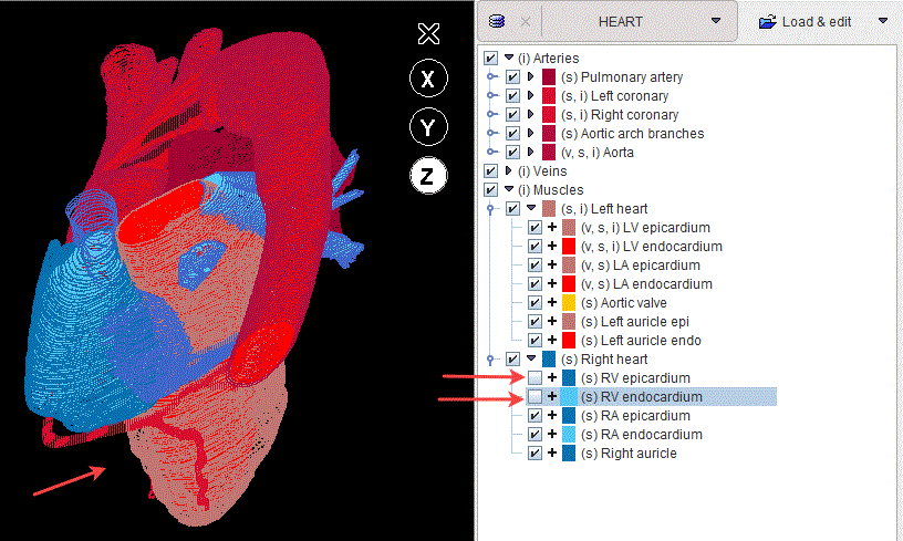
If the selection of a branch is removed, all elements belonging to it will be de-selected.
