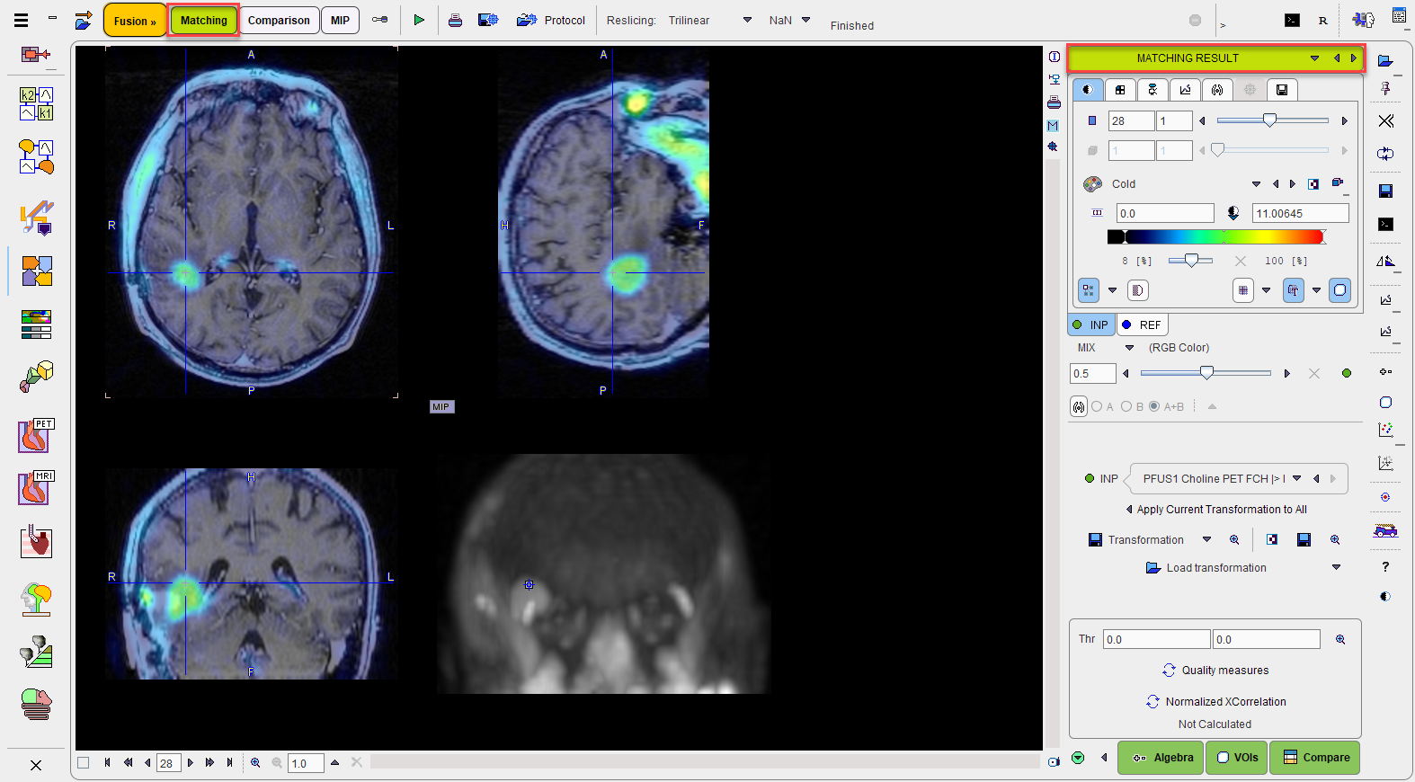
The MATCHED page is illustrated below. It serves for evaluating the matching, manually adjusting the alignment and supports operations with registration transformations.
Fusion Display
The image display on the MATCHING RESULT page shows a fusion of the REF image with the currently selected INP image with the usual image fusion controls.
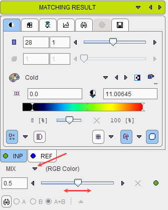
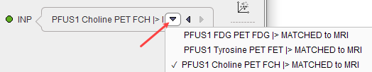
The image used for the fusion display can be selected in the INP list.
Transformations
Each of the INP images has its own spatial transformation which maps the input image from the original space to the reference space. These transformations as well as their inverse are accessible in the expanded control area at the bottom.
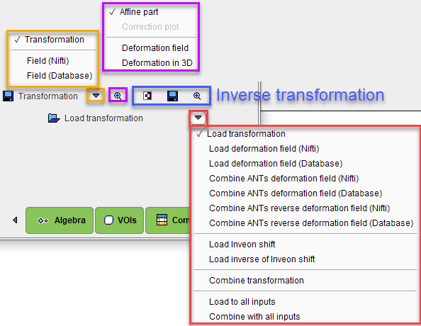
The functionality of these transformation-related elements is as follows:
|
▪ Save the transformation of the current input image. This includes the automatic registration as well as subsequent manual adjustments. ▪For the probability maps normalization two additional options become active under the save selection:the two options allow saving the deformation Field in NIftii or Database format. |
|
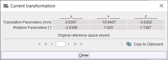
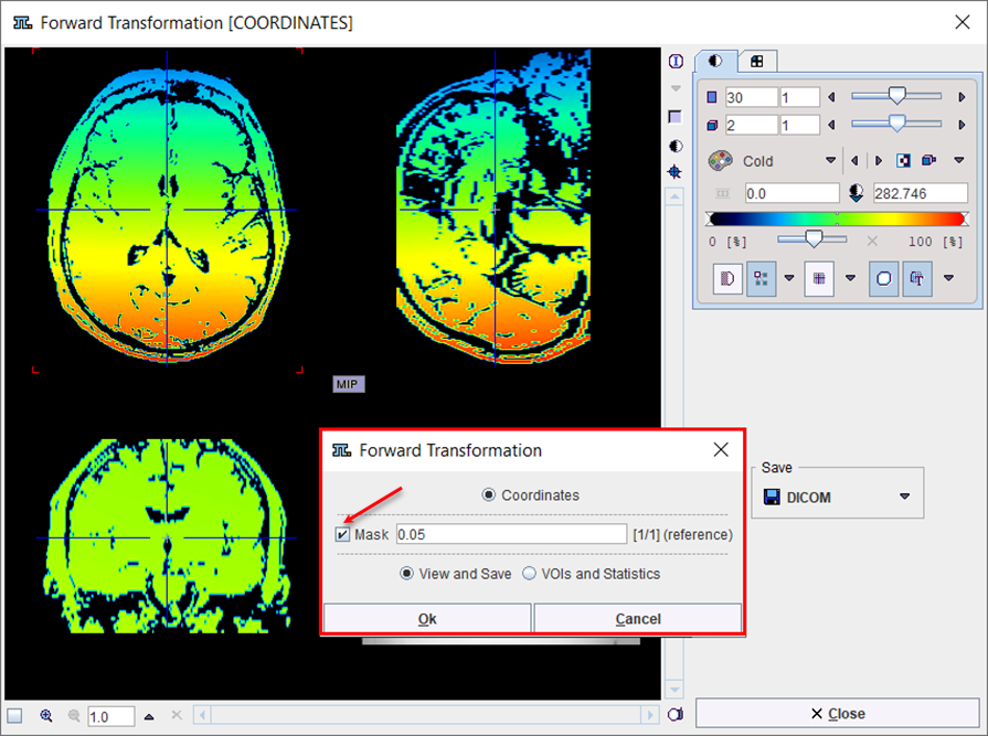
▪ Show the affine transformation part of the current input image in a dialog window ▪ Show the deformation filed of the forward transformation in the three directions, X, Y, Z, as frames. Two options are available for display: the View and Save and the VOIs and Statistics. The Mask option, when enabled, allows visual assessment of the deformation field on the reference image. The View and Save allows visual assessment of the deformation field and saving of the deformation field as an image using the Save panel. Below is shown the result with the Mask option OFF:
Enable the Mask box to view the deformation field on the reference image . Only the pixels with values above the specified value in the text field will be shown for the reference image, e.g 0.05, as illustrated below.
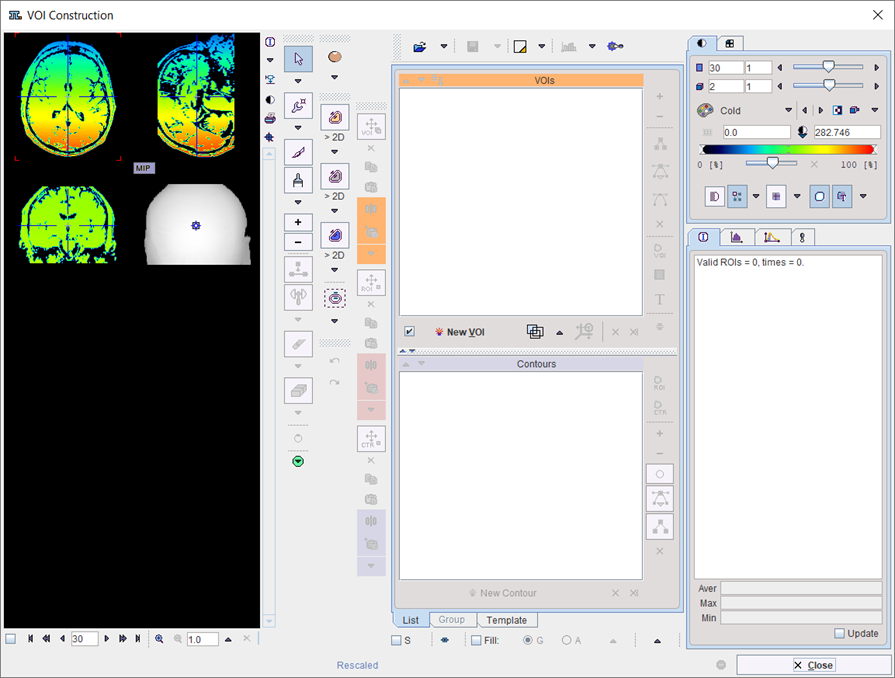
The VOIs and Statistics option opens the VOI Construction interface allowing to outline VOIs for the calculation of statistics for the deformation field. Below the interface appearance with Mask option OFF:
and with Mask (0.05 threshold) option ON:
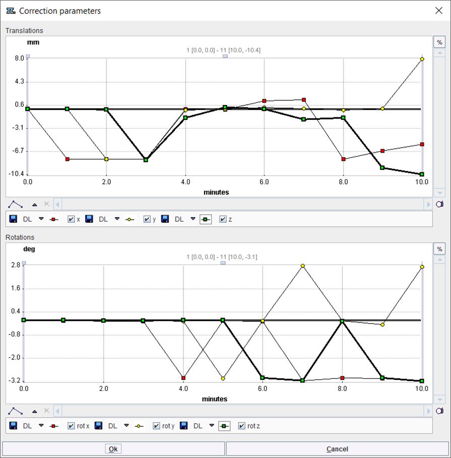
▪ Show the deformation field in the 3D window. ▪ Displays plot graphs of the parameters resulting from the motion correction of a dynamic image
|
|
Calculate the inverse of the current transformation. |
|
Save the inverse of the current transformation. |
|
Show the affine part of the inverse transformation in a dialog window. |
Load Transformation |
Load a transformation, replacing the transformation of the current input image. |
Load Deformation Field (Niftii) |
Load a probability maps deformation field saved in Nifti format, replacing the transformation of the current input image. |
Load Deformation Field (Database) |
Load a probability maps deformation field saved in Database format, replacing the transformation of the current input image. |
Combined ANTS deformation field (Niftii) |
Load an ANTS deformation filed saved in Niftii format and combine it with the transformation of the current input image. Note that the combined transformation becomes the current one and can be inspected with the |
Combined ANTS deformation field (Database) |
Load an ANTS deformation filed saved in Database format and combine it with the transformation of the current input image. Note that the combined transformation becomes the current one and can be inspected with the |
Combined ANTS reverse deformation filed (Niftii) |
Load an ANTS reverse deformation filed saved in Niftii format and combine it with the transformation of the current input image. |
Combined ANTS reverse deformation field (Databse) |
Load an ANTS reverse deformation filed saved in Database format and combine it with the transformation of the current input image. |
Load Inveon shift |
Read the image_ref_shift field from Inveon microPET files and apply it as transformation. |
Load inverse of Inveon shift |
Read the image_ref_shift field from Inveon microPET files and apply the inverse as transformation. |
Combine Transformation |
Load a transformation and combine it with the transformation of the current input image. Note that the combined transformation becomes the current one and can be inspected with the |
Load to All Inputs |
Load a transformation, replacing the transformation of all input images. This makes sense if all input images are in the same space, for instance for a set of parametric maps generated from a single series. |
Combine with All Inputs |
Load a transformation and combine it with the current transformation of each of the input images. |


The button Apply current Transformation to All allows propagating the current transformation to all input series. This operation is applicable if all input images are in the same space. A typical application case is that the registration calculation has been performed with a frame average of a dynamic series, and the result transformation is now applied to the dynamic series itself. Another application case is the matching of a set of parametric maps generated from a single series.
Overlap Indexes
PFUS supports the calculation of overlap indexes as follows: In the Thr area threshold values can be entered for the registered INP and the REF image. Alternatively, the lower threshold of the color table can be adjusted, whereby the Thr values are modified accordingly. The two binary volumes can then be visualized as a fusion image with the ![]() button.
button.
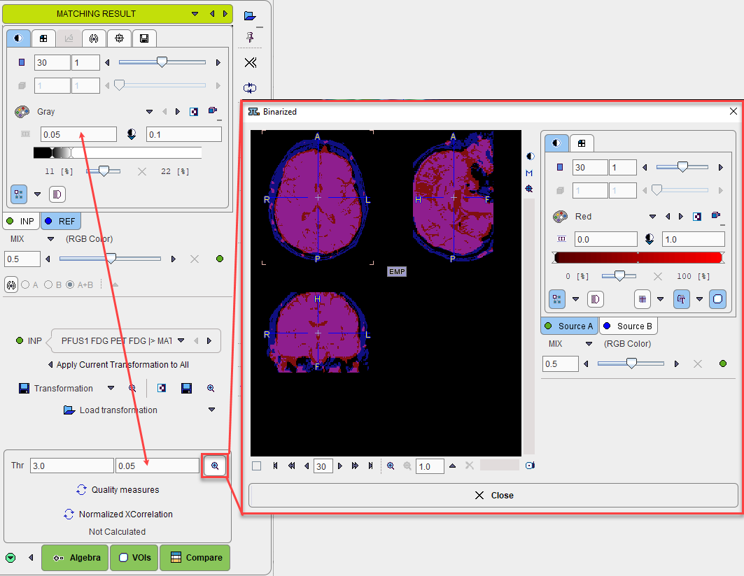
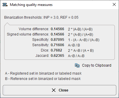
The overlap criteria are then calculated based on the two masks with the Quality measures button.
Normalized XCorrelation
After the matching had been performed, FuseIt supports the calculation of the normalized cross correlation with the Normalized XCorellation button. It shows the correlation coefficient result below:
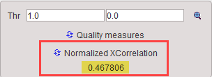
The correlation coefficient is estimated based on the overalpping criteria set in the Thr fields. The closer this value is to 1 the better the matching outcome.
One application for this index could be the selection of the best reference image to be used in the matching procedure. The results of the matching outcome (correlation coefficient) of e.g. INP image to the REF1 and subsequently to the REF2 image should be recorded e.g. in an excel or text file.
Manual Adjustments
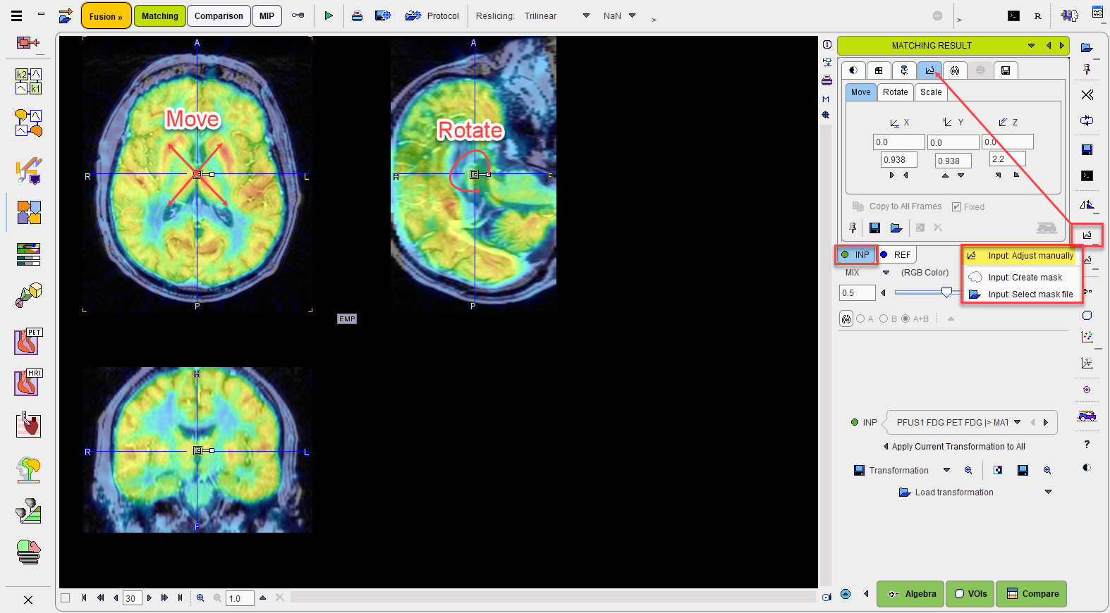
After automatic registration, the input images can be manually shifted and rotated to improve the alignment, if necessary. The same applies, if automatic registration has been skipped altogether in order to perform a fully manual alignment. Manual adjustment is started with the ![]() button in the lateral taskbar as illustrated below. It opens the reslicing tab of the INP images, and shows handles in the image overlay for dragging/rotating the images interactively, as described below.
button in the lateral taskbar as illustrated below. It opens the reslicing tab of the INP images, and shows handles in the image overlay for dragging/rotating the images interactively, as described below.
Action Buttons
Assuming that all input images have been registered to the reference, the user can proceed to the various post-processing pages with the two action buttons
|
Switches to the IMAGE ALGEBRA sub-page for performing pixelwise image arithmetics. |
|
Switches to the VOIS sub-page for outlining VOIs directly in fused images. |
|
Switches to the Comparison page |
Alternatively the main pages Comparison and or MIP can be selected.