As a last resort VOIs can also be created and edited using the standard PMOD VOI tool. It can be started using the three buttons

which are red as long as the VOI definition is empty, and become green afterwards.
Definition of Myocardium
It is recommended to start the VOI definition with myocardium. Selecting the button indicated above opens the VOI definition dialog, showing the MYOCARDIUM short axis images in the axial mode.

Note that all three images (DYNAMIC, BLOOD, MYOCARDIUM) are available during the VOI outlining process. Use the selection indicated above to switch between the images. The availability of the different information has several advantages:
▪The BLOOD images are helpful for defining the RV VOI.
▪Switching back and forth between MYOCARDIUM and BLOOD helps to verify whether the contour definition is adequate in myocardium parts with defects.
▪The DYNAMIC images can be used to check whether there was significant subject motion during the scan. After completing the outlining, simply step through all the acquisitions and look for the relative movement between the contour ad the myocardium.
Note also that the relevant VOIs RV, LV, and EPI/ENDO or Myocard are predefined in the VOI(s) list. We recommend using the output from the automatic VOI generation and adjusting the contours rather than outlining fully manually.
•Adjustment of the automatically created Myocard EPI VOI
1.To inspect the contours switch to the orthogonal view. In each slice the EPI contour is represented by a circular region-of-interest (ROI) which has a 60° angle indicating the septum location.

2.Select the myocard EPI VOI (or ENDO) in the list.
3.To perform global adjustments like shifting and/or scaling a VOI select the VOI Action button
![]()
Drag the VOI with the handle in the center, and scale it by dragging the edges of the VOI bounding box.
4.To reduce the number of contours at the base click into the short axis images, scroll with the mouse wheel to the slices where the myocardium appears in less than a 360°, and then remove the region-of-interest in that slice by selecting the ROI Remove button indicated below.
![]()
Note that this function is only available if the axial plane is active.
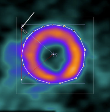
5.To adjust the shape of the contours in individual slices scroll to a slices where the contour needs correction. A global adjustment can be obtained by scaling and moving the ROI. To this end select the ROI Action button
![]()
As a result the ROI Bounding Box is shown in the image.

Now the ROI can be scaled by dragging the edges of the bounding box, and moved by dragging the center handle as indicated above. Fine adjustments can be done with a different tool, the Hammer tool
![]()
Drag the tool against the contour points to push them.

After such adjustments have been done in all slices, the myocardium EPI VOI is ready for further processing.
6.In the case of unsuccessful operations use the undo button
![]()
to go back to the previous state of VOI definition.
•Creating the Myocard EPI VOI Fully Manually
To build the myocard EPI VOI fully manually:
1.Select the myocard EPI VOI in the list.
2.Scroll through the short axis slices until the last basal slice with 360° myocardium is shown.
3.Select the Outline polygon, adjust the vertices tool
![]()
and click along the EPI contour

closing the contour by clicking at the first point or selecting the Finish button. Immediately, the septal 60° angle is shown.
4.Ensure that the septal angle points to the left where the RV should be located. To be able to adjust the angles, select the ROI action tab, so that the bounding box of the ROI is visible. Then, drag the connection of the septal angle with the bounding box as indicated below so that a 60° angle is enclosed as indicated below. This adjustment must be performed for each slice separately.
5.Scroll to the next slice towards the apex with the mouse wheel, perform the outlining process, and repeat until the EPI contour is defined in all relevant slices.
CAUTION: Polar sampling is currently only supported when the number of vertices is identical for all contours. If this is not the case, the polar plot of the dynamic data can not be shown, and the sector TACs are calculated by averaging the activities of voxels alongside the contour.
The VOIs in the right and left ventricular cavities are much easier to define.
•Creating the LV VOI Manually
1.To navigate to the location of the left ventricle make sure the display shows the orthogonal slices.
2.Adjust the colors so that the location of minimal activity in the left ventricle becomes dark.
3.Select LV in the VOIs list. If the myocardium EPI (or ENDO) VOI is still selected, it will be overwritten by the following actions.
4.In the SA images scroll to a slice showing minimal activity in the LV.
5.Click into the dark area of the LV.
6.Select the Circle (contour ROI) ![]() and define a radius with the Circle box enabled.
and define a radius with the Circle box enabled.
7.Activate the Apply button. A circle ROI is drawn. If necessary decrease/increase the radius value and Apply again. Make sure it stays in the center of the cavity to minimize the spillover from myocardial activity.
8.Repeat this process in some of the neighboring slices, until a representative VOI has been defined towards the base:

CAUTION: The activity concentration calculated in the LV serves as the input curve during the quantification process. Any underestimation of the input curve will directly translate into an overestimation of the calculated flow in all segments. Therefore, an accurate placement of the LV is of utmost importance!
•Creating the RV VOI Manually
1.To navigate to the location of the right ventricle make sure the display shows the orthogonal slices.
2.Select RV in the VOIs list. If the myocardium EPI VOI is still selected, it will be overwritten by the following actions.
3.Select the 2D cold Iso-contour tool ![]() .
.
4.In the SA images scroll to a slice showing the the RV clearly.
5.Click into the dark area of the RV. An iso-contour ROI is drawn. Make sure it is not too close to the septum to minimize the spillover from myocardial activity.
6.Repeat this procedure in some neighboring slices, until a representative VOI has been defined:

7.To check the location of the VOI, switch the display to the BLOOD images.
VOI Saving
The saving button
![]()
in the VOI tool allows to explicitly save the current VOI definitions in a file. However, the VOIs will also be part of a saved protocol.
After all VOI definitions have been completed, select the Ok button of the VOI dialog window to return to the cardiac tool and continue the analysis.