When arriving at the VOIs sub-page a fusion image is shown to the left which is composed of the Mag and the FLOW MASK (Angio) images. Note the two panels A and B in the upper right which correspond to those images, and the slider for mixing the respective contributions in the fusion image.
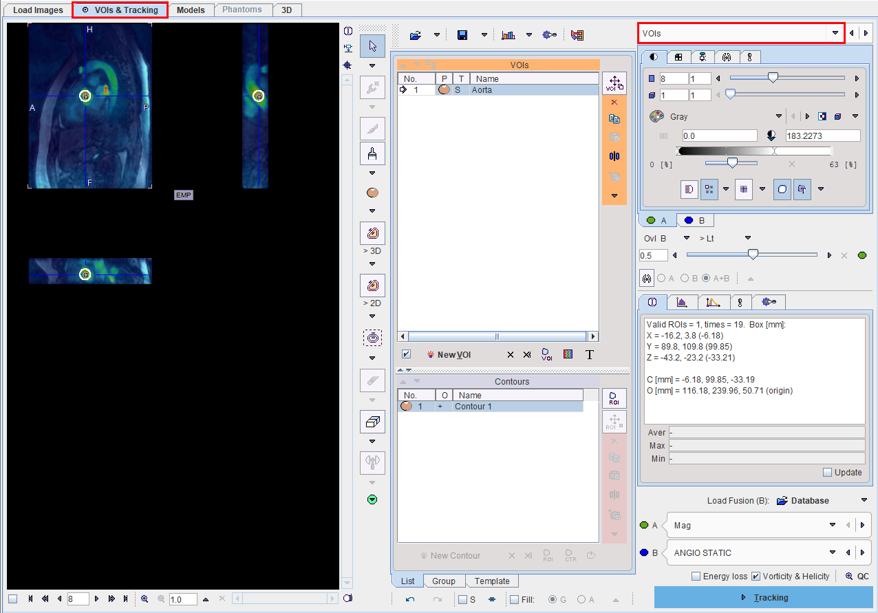
In the lower right, the A and B images can be redefined.
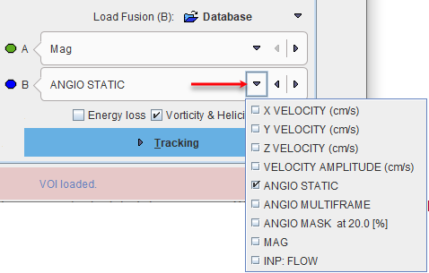
The choices are
▪the flow VELOCITY components in the different directions X, Y, Z,
▪the VELOCITY AMPLITUDE (length of velocity vector).
▪an image ANGIO STATIC resembling an angiographic image (calculated by summing SQRT(VELOCITY* MAGNITUDE) over time),
▪an image ANGIO MULTIFRAME
▪a masked version of ANGIO STATIC at the 20% threshold level,
▪the MAG
▪the INP:FLOW
VOI Definition
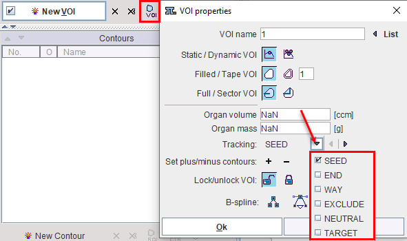
The calculation of streamlines is based on VOIs which can play different roles:
▪SEED VOIs: Streamlines tracking is started from the pixels in seed VOIs, following the local velocity vector directions.
▪END VOIs: Only streamlines ending in this VOI will be used. To avoid excessive pruning of streamlines, an END VOI should have sufficient volume.
▪WAY VOIs: Only streamlines passing through the WAY VOI will be used.
▪EXCLUDE VOIs: streamlines passing through an EXCLUDE VOI will be removed.
▪NEUTRAL VOIs: Such VOIs have no impact on streamlines tracking. Setting VOIs to NEUTRAL allows assessing the effect of END, WAY and EXCLUDE VOIs without the need of removing them.
▪TARGET: Is representing a VOI the track should end with.
VOIs can be created with the usual PMOD VOI tools. When creating a new VOI, a dialog window pops up which requires defining the appropriate Tracking property. Later on, this property can be changed using the VOI properties functionality as illustrated below.
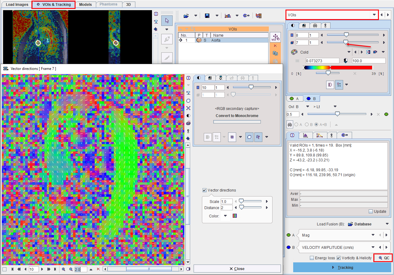
Note the check boxes Energy loss and Vorticity&Helicity. If they are checked, PGEM calculates energy loss map and Vorticity Amplitude and Absolute Helicity parametric maps, respectively. Vorticity is a measure of rotation, whereas helicity relates to the knottedness in fluids, and they can be used for assessing the degree of flow non-laminarity.
Vector Inspection
The loaded velocity vectors can be inspected with the QC button. It shows a window with the projection of the flow direction vectors together with a color-coded direction image. Red indicates diffusion along the x-axis (left-right), green diffusion along the y-axis (posterior-anterior), and blue diffusion along the z-axis (inferior-superior).
Note that the time frame has to be selected before starting Vector QC, as the velocity vector field is four-dimensional.
Please proceed with the ![]() button in the lower right.
button in the lower right.