When arriving at the SEGMENTS panel, a fusion of the PET image with the CT is shown in an orthogonal layout.
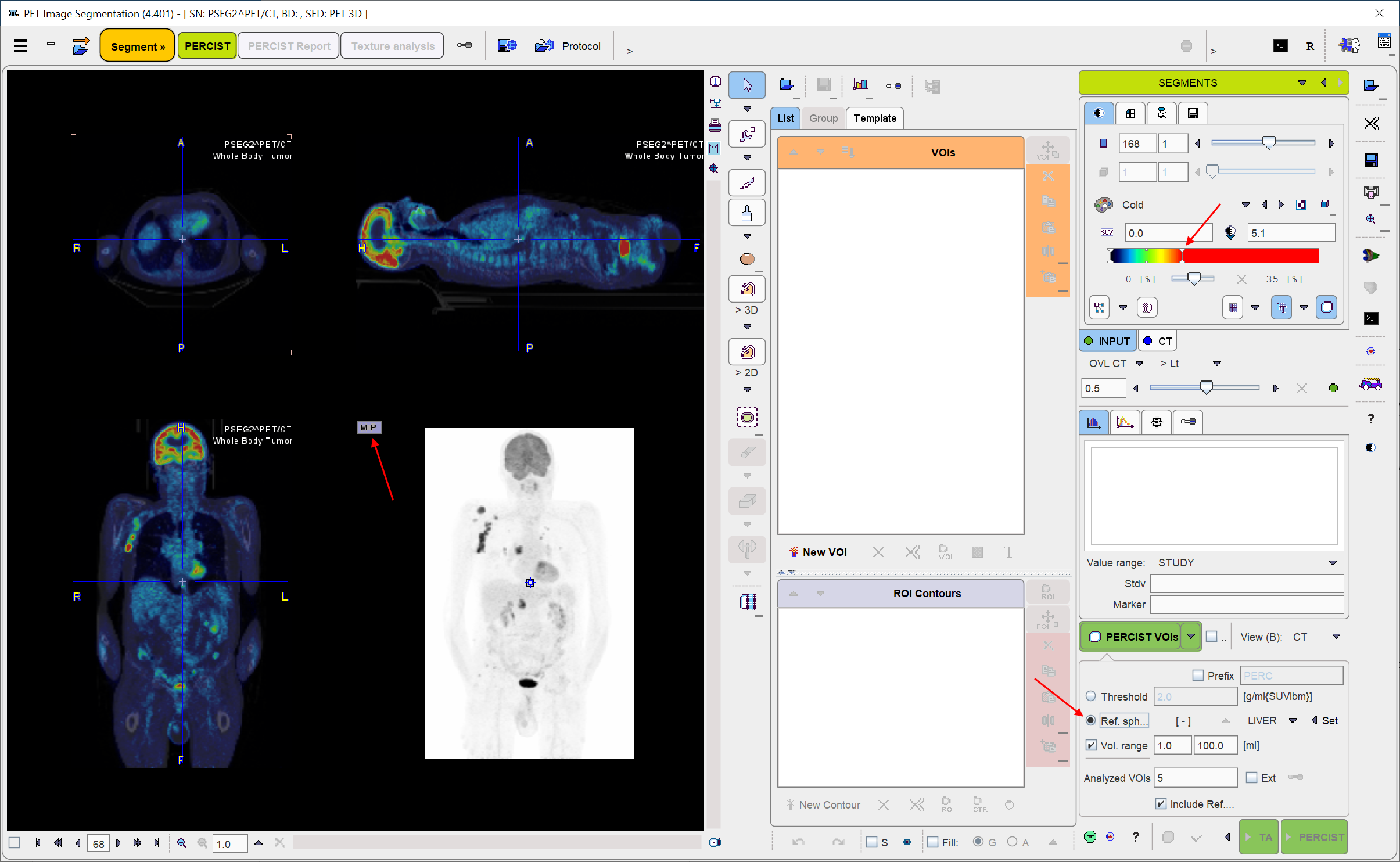
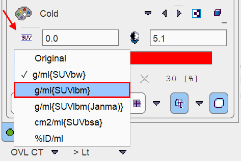
For a dedicated PERCIST analysis the INPUT (e.g. PET) image should be displayed in SUVlbm units. If this is not the case, the display units should be switched accordingly. Note that SUVlbm requires weight and height to be defined in the data.
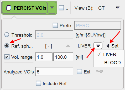
It is also recommended to adjust the settings of the color bars, the fusion slider, and the MIP to optimize the image display. The relevant user elements are indicated by the arrows above. Please refer to the PMOD Base Functionality Guide for details. In order to adjust the CT the corresponding tab has to be selected first.
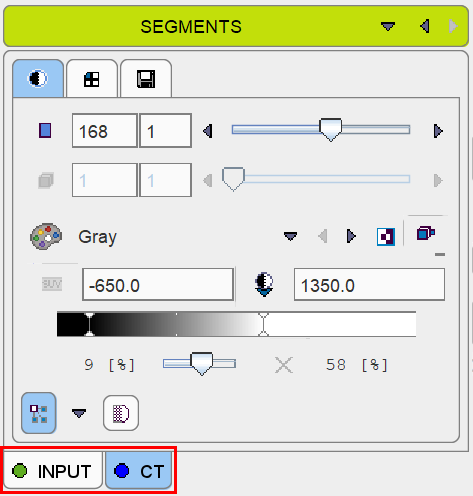
However note that before starting the segmentation procedure, it is important that the INPUT image tab is again selected.
![]()
Otherwise the segmentation will fail, as it will operate on the CT image.
Reference Sphere Placement
First, the Ref. sphere radio button needs to be selected. It has a related option button to choose whether the reference is placed within the LIVER or the BLOOD pool.
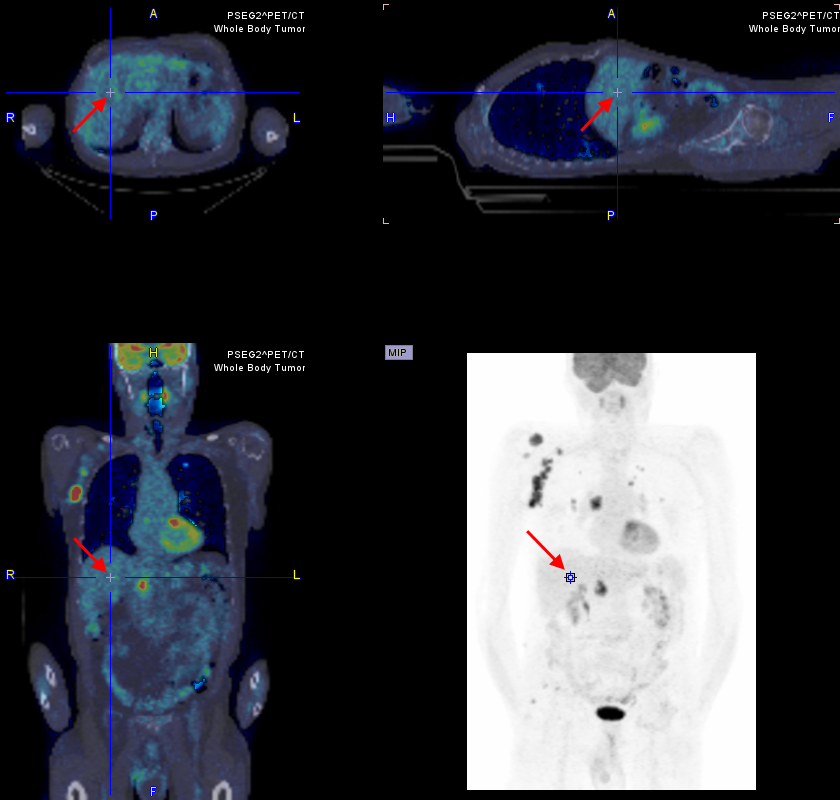
Next, in the image area, the position has to be triangulated where the reference sphere is to be placed. The easiest approach is to first click into the MIP image for rough localization, and then into the planar images for fine tuning.
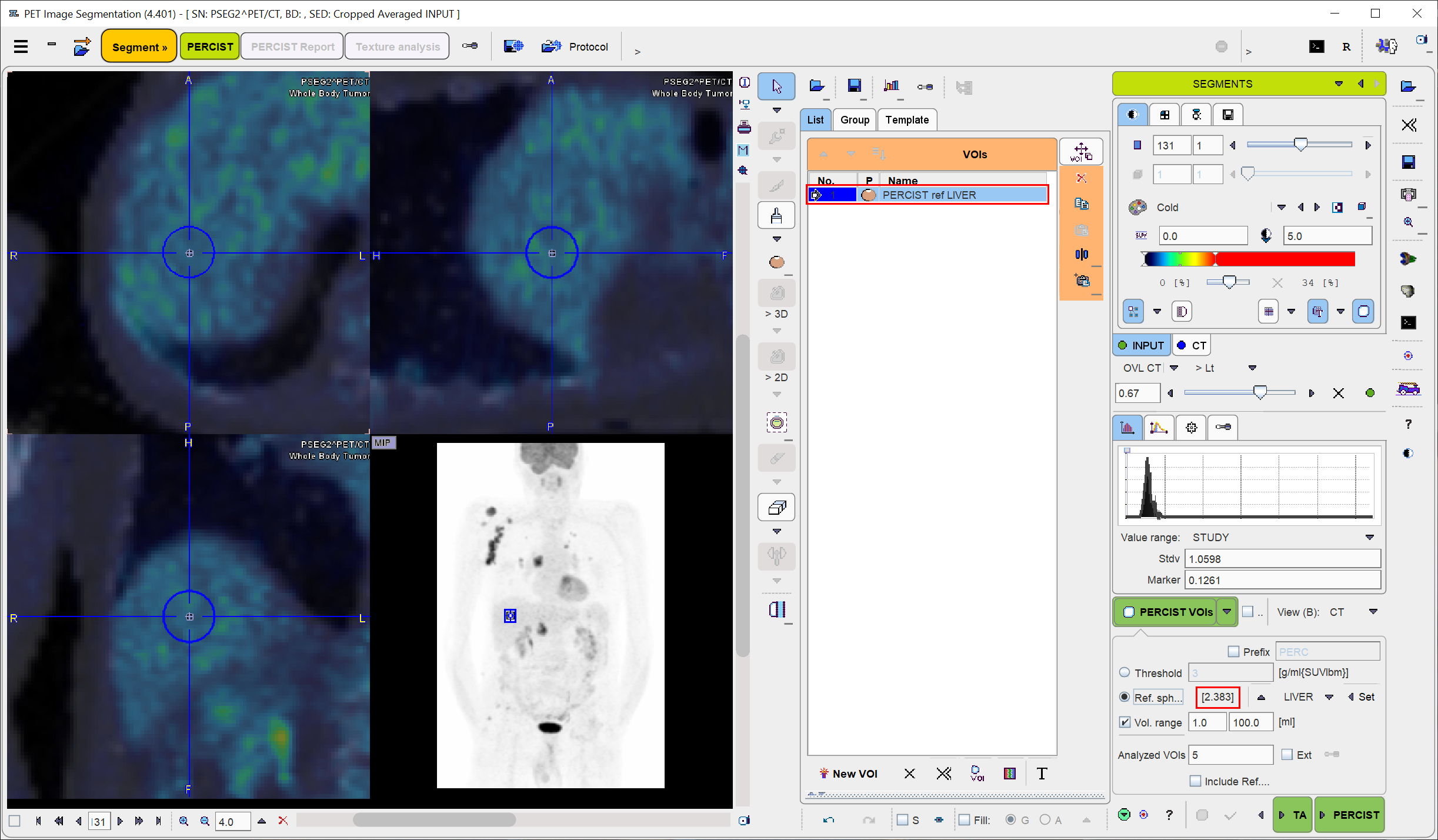
When the triangulation point is properly localized, use the Ctrl+Shift+U keyboard shortcut or the Set button for generating the reference sphere. The result for the situation above is illustrated below, with the image zoomed by a factor of 4. Note the PERCIST ref VOI in the VOIs list, and the threshold of 2.764 SUVlbm which was calculated as the minimal level of tumor uptake. With the LIVER setting it is obtained by 1.5 times the average plus twice the standard deviation within the sphere. In the BLOOD case it will be twice the average plus twice the standard deviation.
Automatic VOI Generation
For PERCIST the iso-contouring threshold is adaptively obtained from the reference VOI as described above. In other contexts it may be preferable to use a fixed Threshold, for instance 3.0 SUVlbm as illustrated below.
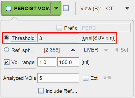
Note the up-arrow which transfers the Ref. sphere determined value to the Threshold field.
The PERCIST VOIs button starts the iso-contouring of the PET image at the configured threshold. Note that it only considers voxels within the defined mask, and returns the segmented objects as a list of VOIs, sorted by decreasing SUVpeak.
Some options modify the behavior of the VOI generation:
•Prefix: If the box is active, all VOIs are named with the string provided in the text field and an incremented number.
•Appending: If the A box is enabled, new VOIs are appended to the existing VOIs list. Otherwise, the existing VOIs are first removed.
•Vol. range: If this box is enabled, the two entered numbers define the minimum and maximum volumes of the detected VOIs. This feature is useful for omitting tiny spots or large accumulations such as the brain, heart or bladder.
VOI Selection and Removal
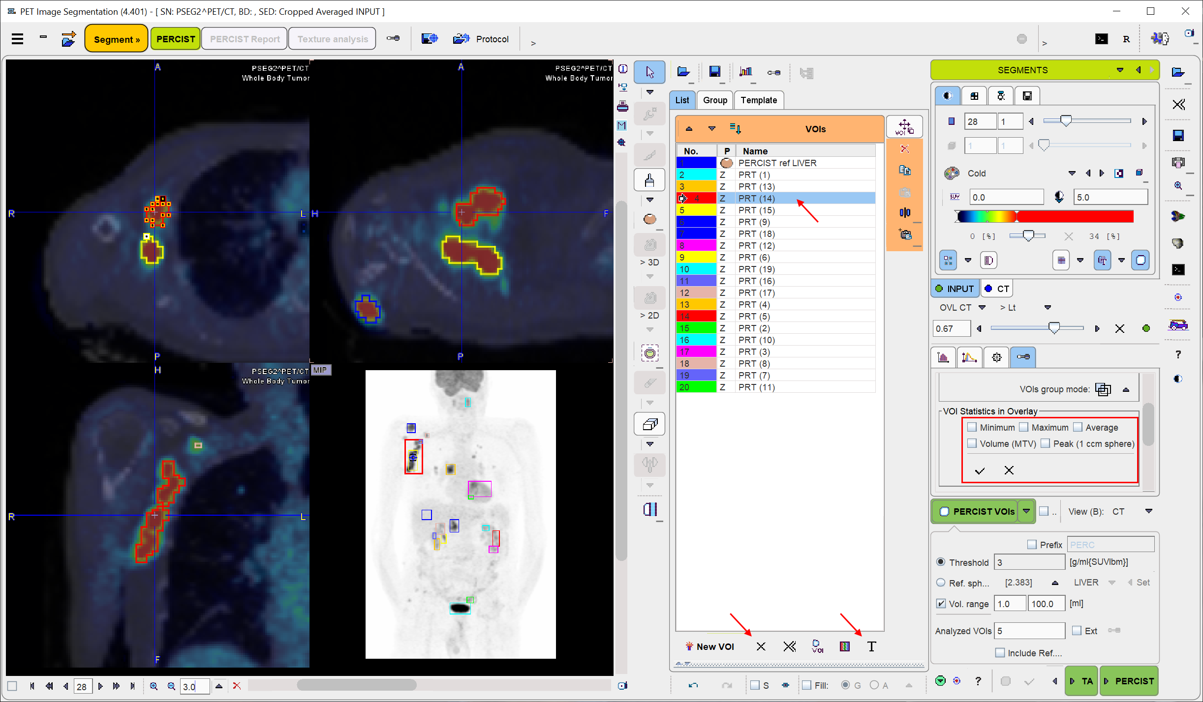
When clicking at a VOI in the list, the lesion is triangulated in the display. If some VOI statistics in the overlay elements are enabled, the results for the selected VOI are shown in the overlay.
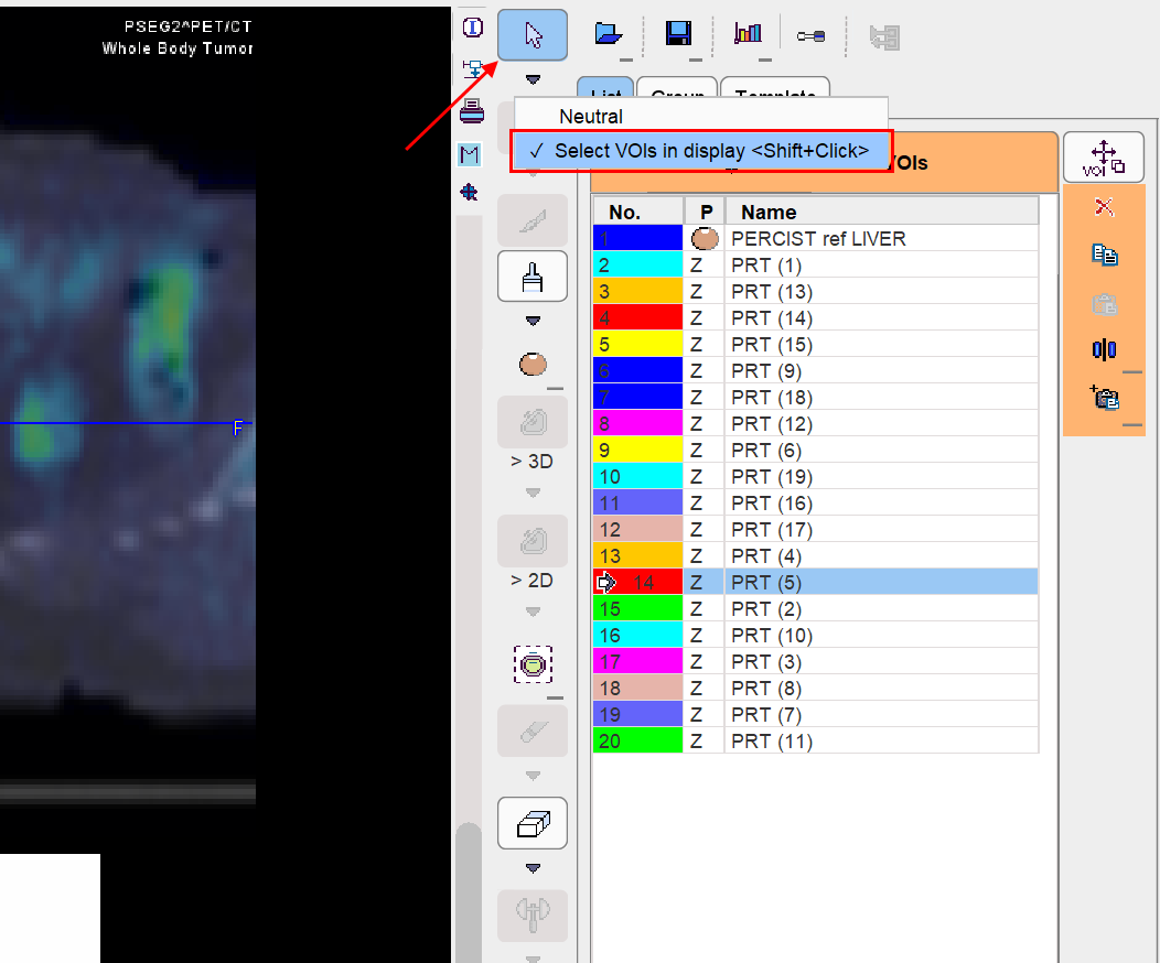
As automatic contouring may result in VOIs which are not relevant, targeted VOI selection and removal is an important task. Direct localization within the image is a more more intuitive way of VOI selection than clicking into the VOIs list. This is possible after setting Neutral mode button to Select VOIs in display as illustrated below. Thereafter VOIs (e.g. the bladder) can be selected by clicking at them in the MIP or in the planes. Then, the selected VOI can be removed from the VOI list by the ![]() button.
button.
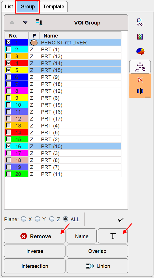
By holding done the Shift key it is furthermore possible to select multiple VOIs. On the Group panel they appear as marked entries as illustrated below. There, the Remove button removes all marked entries. Note also the T button which allows renaming all of the selected VOIs in a structured way as described below.
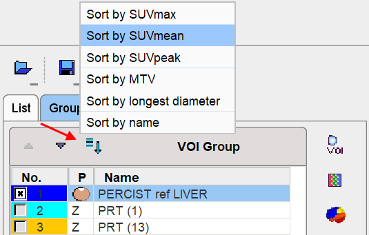
VOI Sorting
Sorting of the lesion VOIs according to various criteria is possible via the option button above the VOIs list. The sorting order is relevant for the PERCIST report, as it includes the uppermost entries in the list.
VOI Labeling
The automatically generated VOIs are simply numbered. In order to generate a useful report it is recommended to assign more informative names. VOI names can interactively be edited in the list.
Alternatively, predefined names can be used either by right-clicking into the VOI list,
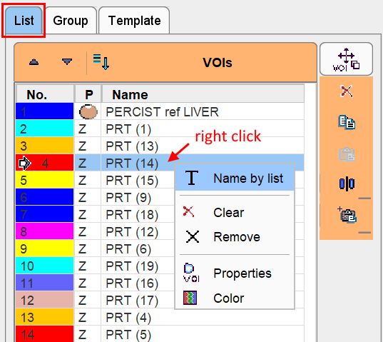
or by selecting a VOI in the list and activating the T button below the list. A dialog window is opened as illustrated below.
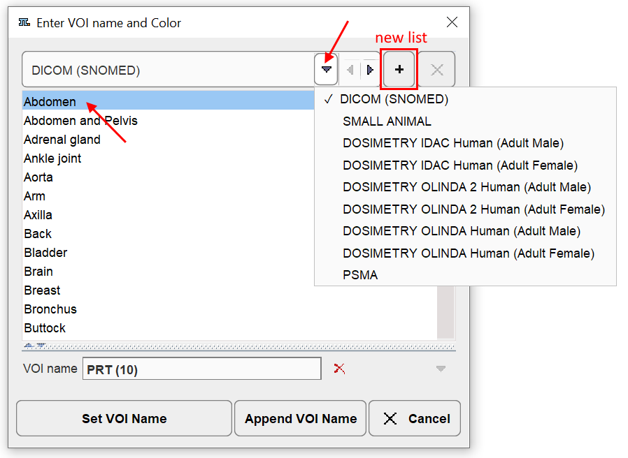
Several lists containing predefined names are available and can be selected at the top. By clicking at a name in the list, the VOI name field is updated. Set VOI name (or double-click) replaces the name of the selected VOI, whereas Append VOI Name adds the string to the present VOI name.
It is easy to prepare user-defined lists such as PSMA in the example above. To do so, process an arbitrary data set and name the VOIs meaningfully. Then activate the + button of the window indicated above. A new dialog appears which shows the VOI names to become the list entries, and requests a list name. After saving, the list will be present as a new entry in the list selection.
There is a specific convention for creating names which produce a tree structure on the Group panel. As an example, the PSMA list entries may look as follows.
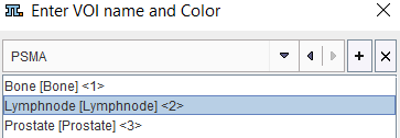
They follow the naming structure "Label1[label2]<number>" which allows generating VOI groups and label maps.
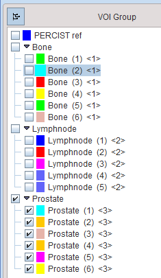
The T naming feature is also available on the Group panel to label multiple VOIs at once. For instance, a selection of VOIs is assigned the Bone[Bone]<1> name in the example below.
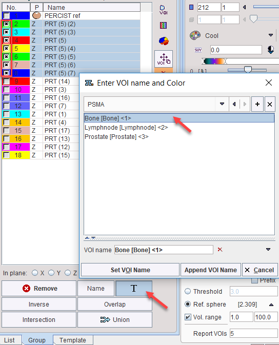
The other VOIs are similarly assigned to the Lymphnode and Prostate entries. These operations create the following tree structure of VOIs with the first label as the root name, and the second label as the branch names numbered from (1).
The numeric label between the <> brackets at the end of the VOI name will be used at the time a label map is created from the VOIs (not yet available).
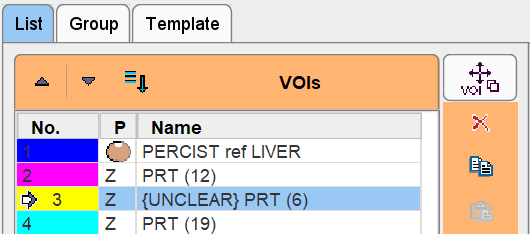
There is a particular VOI naming feature intended for labeling VOIs which need further evaluation. When hitting the Ctrl+Shift+B keyboard shortcut, the tag {UNCLEAR} is added to the name of the currently selected VOI as illustrated below. The shortcut works as a toggle: if it is hit again, the tag is removed. VOIs tagged with {UNCLEAR} in the list have a particular behavior in sorting operations. Independent of the order they always stay at the top with the idea that the user has to clarify the nature of the lesion.