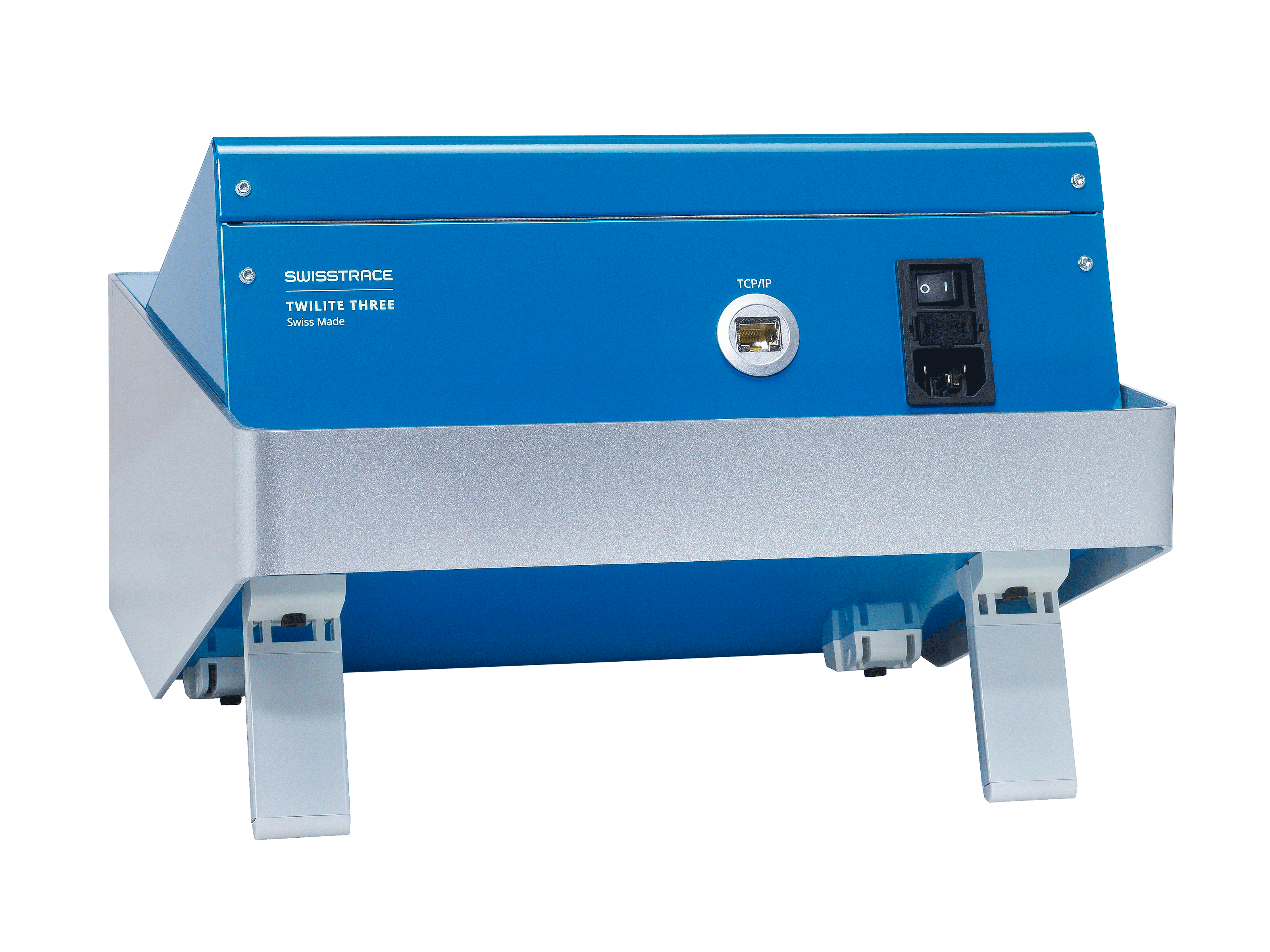
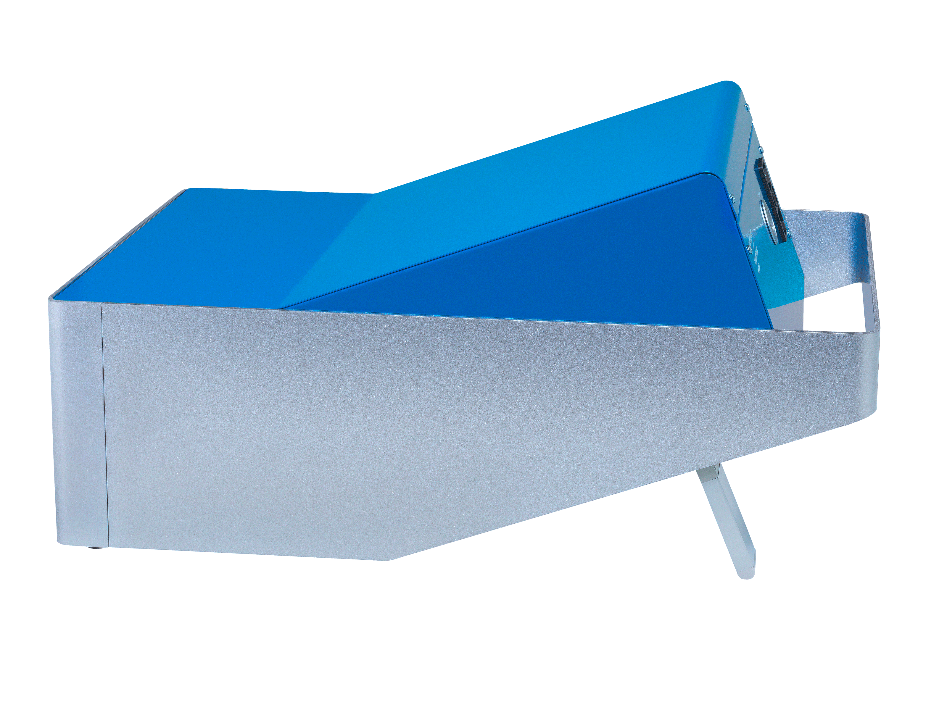
The ON/OFF power switch can be found on the rear panel of the base unit. The base unit can be connected to the acquisition computer with a standard network cable. Alternatively, it can be connected to a network switch, and a remote computer used for the acquisition (configuration by DHCP is possible). The twilite three base unit can be used with tilted front panel (e.g. when used on a bench top and viewing from above) or with vertical front panel by extending the support legs (e.g. when placed on top of a rack, facilitating viewing from below).
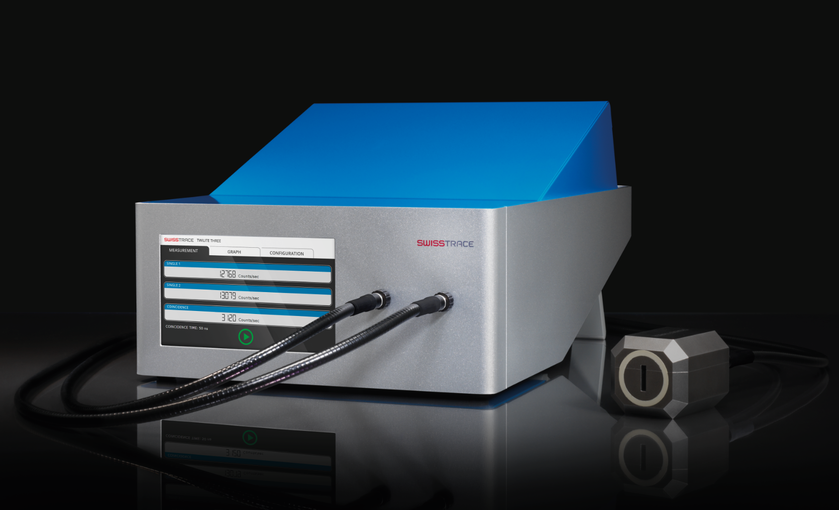
On the right of the front panel there are two connectors for the attachment of the light guides to the measuring head.
The light guides are connected to the base unit and detector head with aluminium screw fittings. Note that the screw fittings are different at each end of the light guides. The textured fitting should be connected to the base unit, and the smooth fitting to the detector head (note that the textured fittings will also not fit side-by-side at the detector head). Care should be taken not to over tighten the fittings, as damage to the screw threads may occur. No tools should be used to tighten the fittings. Initial installation and connection of the light guides will be performed by a swisstrace engineer.
Note: Care should be taken not to touch or contaminate the quartz end faces of the light guides.
The outer coating of the light guides should only be cleaned with a soft cloth and water.
The touch-screen on the front panel serves as the user interface and displays the current status as well as the instantaneous measurements.
In PET/MR installations, two-piece light guides are recommended, connected by an optical coupler (pictured below). The optical couplers can be mounted in a filter plate in the Faraday cage, as illustrated below. This requires a 20 mm hole for each coupler. Alternatively the couplers can be positioned close to the Faraday cage and the light guides routed through a wave-guide tube. The light guides are connected to the optical couplers using the same screw-fitting interface as for the detector head and acquisition box. Spacers should not be added to the optical couplers as this may result in non-contact of the quartz optical surfaces and loss of sensitivity.

The two parts of the optical couplers, illustrating how they can be screwed into a filter plate.
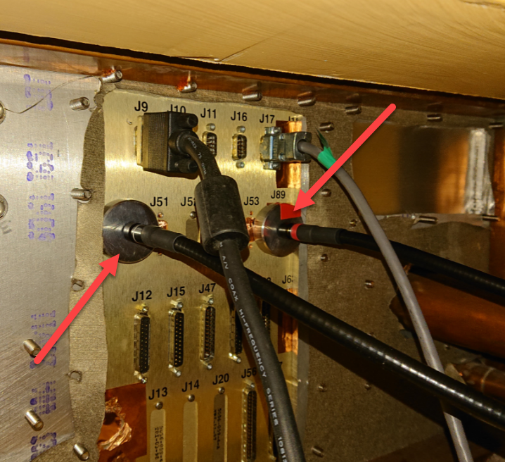
The optical couplers mounted in a filter plate (viewed from the operator room of the PET/MR).